

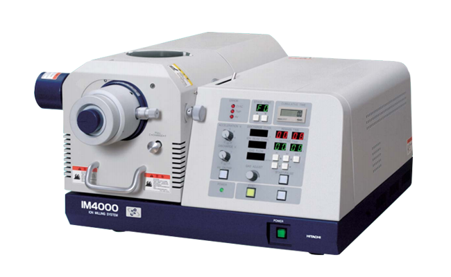
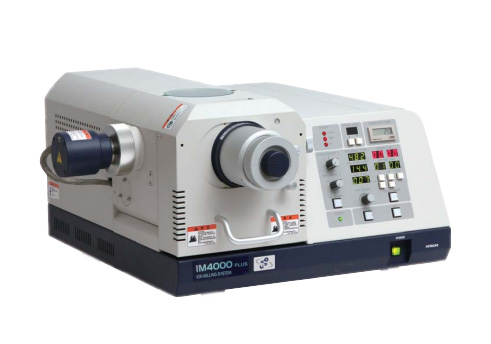
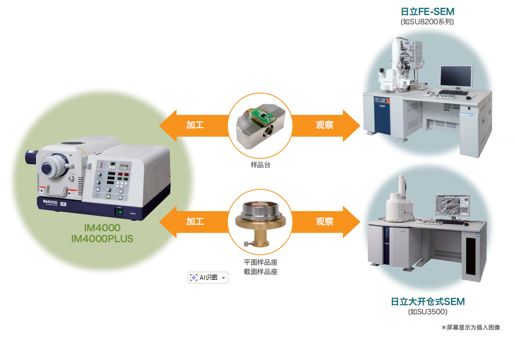
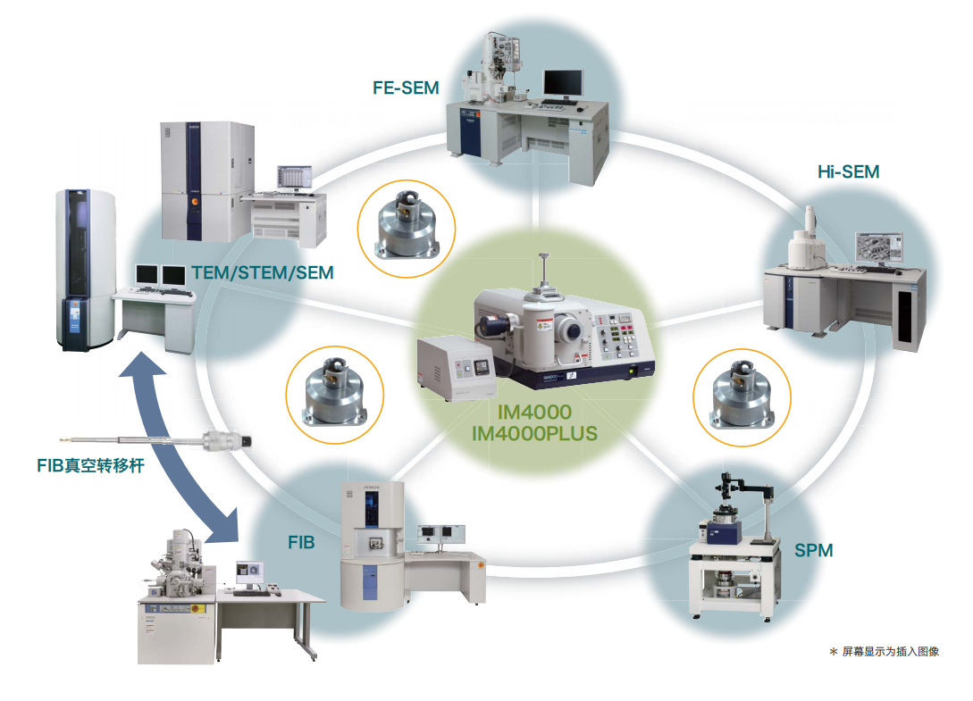
One instrument has both "Cross Section Milling" and "Flat Milling" functions. By replacing the sample holder, it can meet a wide range of application needs.
● IM4000PLUS has a higher processing speed
● Used in conjunction with Hitachi SEM
● Intermittent processing reduces thermal damage
One instrument has both "Cross Section Milling" and "Flat Milling" functions. By replacing the sample holder, it can meet a wide range of application needs.
In order to observe and analyze the internal structure of the sample, it is necessary to expose the internal structure of the sample.
AI image recognition and cutting or mechanical grinding of cross-sections inevitably result in deformation and damage due to stress, making it difficult to obtain the smooth surface required for SEM analysis.
The Hitachi ion milling device uses a large-area low-energy Ar ion beam to process stress free cross-sections, providing an effective pre-treatment method for SEM observation of the internal multilayer structure, crystalline state, foreign object analysis, layer thickness measurement, and other aspects of the sample.
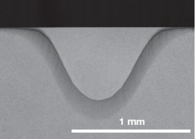
A mask is placed between the sample and the ion gun, with the upper end of the sample slightly protruding from the mask. The ion beam is irradiated onto the sample from above the mask and processed along the edge of the mask to create a flat cross-section.
● The low damage cross-section made facilitates the analysis of internal structures below the surface layer.
● Applicable samples: electronic components such as IC chips, PCBs, LEDs, etc. (multi-layer, crack, hole analysis), metals (EBSD crystal structure, EDS elemental analysis, coating), polymer materials, paper, ceramics, glass, powders, etc.
● The movable sample holder can accurately locate and achieve grinding at specific positions (see instructions for details).
● Maximum sample: Width 20mm x Length 12mm x Thickness 7mm
● The combined sample stage does not require replacement between mechanical grinding, ion grinding, and SEM observation (Hitachi models).
Sample: Thermal paper
Cross section after blade cutting
Cross section after ion milling
SEM requires special sample preparation methods to observe metallographic structures and material defects. Traditional mechanical grinding and polishing can cause deformation, damage, or scratches on the surface, making it impossible to obtain the true structure of the sample. The Hitachi IM4000 can be used for stress free processing of samples, which can be used to remove the surface layer of the sample, process low damage planes, and also for subsequent machining processes of mechanical grinding.

If the central axis of the ion beam and the rotation axis of the sample stage are consistent, the processed contour reflects the distribution of ion beam current density, that is, the shape with a deeper central part. The flat grinding method utilizes a certain eccentricity between the ion beam center axis and the sample stage rotation center axis to obtain a uniform large-area machined surface.
● Uniform processing range with a diameter of approximately 5 mm
● Able to remove minor damages and deformations that are difficult to remove by mechanical grinding
● Large area grinding that can be used for various analytical purposes
Observation of crystal grain boundaries and multilayer films:
When the ion beam irradiation angle is small, the processing rate of the ion beam is highly correlated with the crystal orientation and composition of the sample. By using the difference in processing rate, a flat surface resembling a relief can be processed.
Interface observation, element analysis, EBSD * analysis:
When the ion beam irradiation angle is large, the processing rate of the ion beam has little correlation with the "At" and "composition", and a flat sample surface can be processed.
● Maximum sample size: diameter 50 mm x height 25 mm
● There are two options for rotary machining and swing machining:
In addition to the rotary machining method, a swing machining method has also been added, with a swing angle of ± 60 or ± 90 degrees. Multiple processing methods (adjustable speed and rotation) can be selected to produce relatively flat surfaces.
Sample: Steel
After mechanical polishing
After planar ion milling
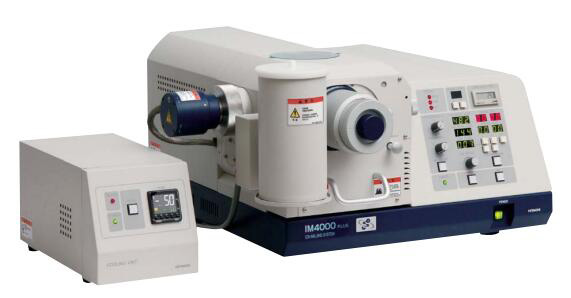
IM4000PLUS has increased the density of ion beam, resulting in a significant increase in grinding rate. (Grinding rate: 500pm/hr, increased by 50% * 1 compared to IM4000 @ acceleration voltage 6kV, Si material)
IM4000PLUS
Sample: Si sheet
IM4000PLUS processing results
● The sample ground by IM4000/IM4000PLUS can be directly placed into Hitachi SEM for observation without removing the sample from the sample stage.
● Both the flat sample holder and the cross-sectional sample holder can be placed in the Hitachi large open warehouse SEM for direct observation.
● After SEM observation, it can be ground again.
● Use a differential ruler to adjust the mask and finely adjust its position.
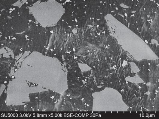
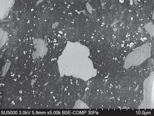
The ion beam automatic switch can effectively reduce sample thermal damage.
Sample: Lead containing solder

Continuous processing

Intermittent processing
BSE image
SEM: SU5000
IM4000PLUS equipped with low-temperature control function
During ion milling, the sample processing area is cooled using a liquid nitrogen cooling device.
The use of cooling systems is highly effective for thermal sensitive materials.
The temperature control system can prevent the material from cracking after excessive cooling.
Sample: Silicone
No cooldown
There is cooling
BSE image
SEM: SU5000
If it is necessary to avoid contact between the sample and the atmosphere, a vacuum transfer box unit can be selected.
The sample in the vacuum transfer box can be directly transferred to the vacuum chamber.
Therefore, samples processed by IM4000/IM4000PLUS can avoid contact with the atmosphere and be directly transferred to SEM * 1, FIB * 1, or SPM * 2.
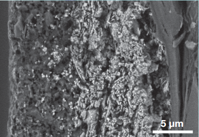
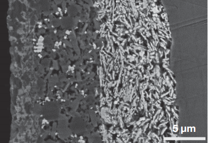
Sample: Lithium battery negative electrode (after charging)
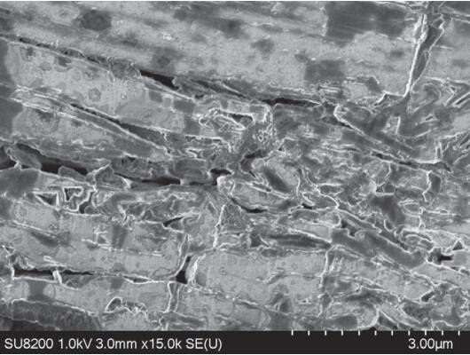
No vacuum transfer box protection
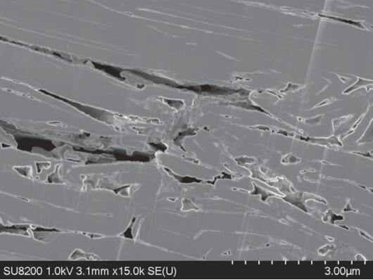
There is a vacuum transfer box for protection
SE image
SEM: SU8200 series
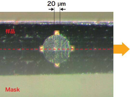
The cross-sectional sample stage is equipped with improved high-precision positioning tools * 3.
Adjust the differential ruler knob to accurately position the mask. The following figure shows the TSV grinding results of Mask placed at the red line position (with a center position of 20 μ m pad).
3: Higher movement accuracy than existing cross-sectional sample holders
Sample: TSV (Through Silicon Via)
Fine tuned mirror image
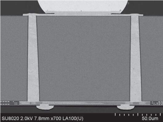
After section grinding
BSE image
SEM: SU8020
In order to accommodate higher grinding processing rates, the hardness of the superhard alloy Mask is twice that of the standard Mask, allowing it to withstand longer ion beam grinding times.
Sample: Hard alloy drill bit, grinding time: 4h
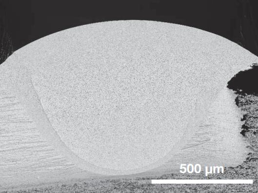
Sectional grinding area
Enlarged left image
BSE image
SEM: SU5000
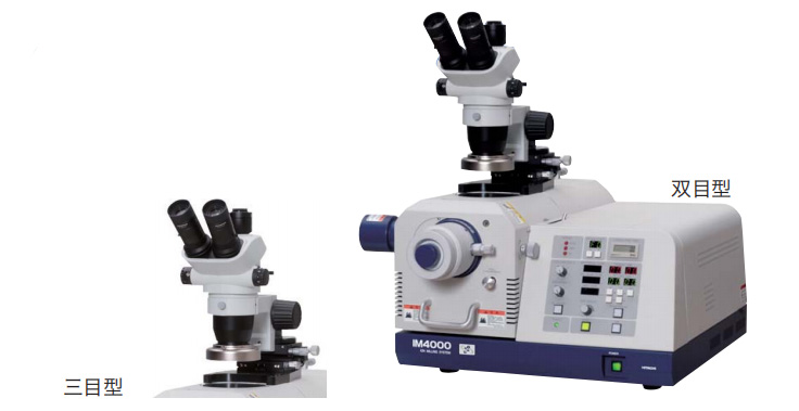
A microscope (optional) for real-time observation can be installed to achieve 15-100 times real-time observation.
In addition, the three eye microscope can be equipped with a CCD camera for observation on the display (optional) * 4.
The CCD camera and monitor are purchased locally
Sample: Lead containing solder
BSE image
SEM: SU5000
Sample: Neodymium magnet
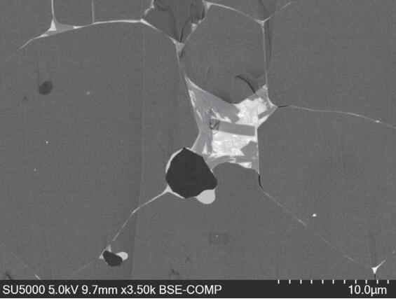
BSE image
SEM: SU5000
Sample: Lanthanum-doped Ceria
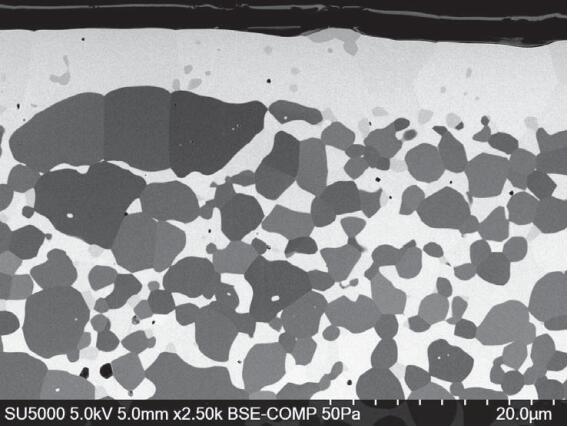
Sample provided by Prof. Katsunori Hanamura, Tokyo Institute of Technology
BSE image
SEM: SU5000
Sample: Nanocolumns
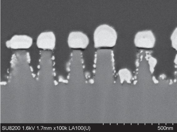
Sample provided by Prof. Masahiko Yoshino, Tokyo Institute of Technology
BSE image
SEM: SU5000
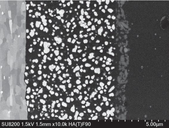
Sample: Thermal paper
BSE image
SEM: SU8200 series
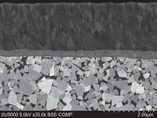
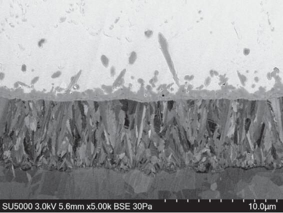
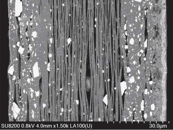
Sample: Coating
BSE image
SEM: SU8200 series
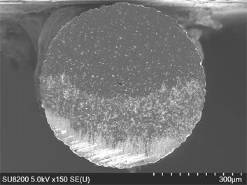
After flat grinding of carbon fibers, the possible polymer buckling structure caused by polyacrylonitrile fibers during spinning was observed.
Sample: PAN (polyacrylonitrile) carbon fiber
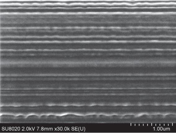
Before ion milling
SE image
SEM: SU8020
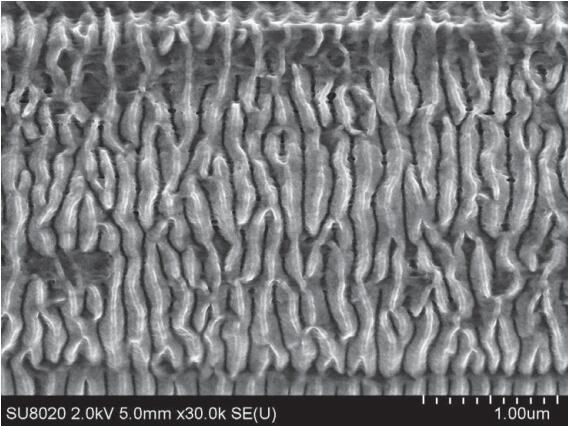
After ion milling
SE image
SEM: SU8020
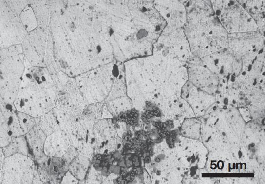
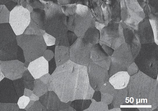
The metallographic observation after mechanical polishing shows obvious scratch damage, but it can be well observed after ion grinding.
Sample: Chromium molybdenum steel
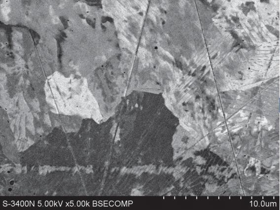
Before ion polishing (surface mechanical polishing)
BSE image
SEM: S-3400N
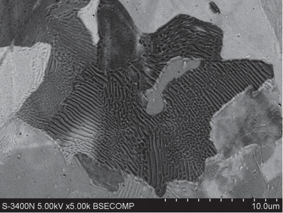
After ion milling
BSE image
SEM: S-3400N
After FIB processing, the doping layer cannot be observed, but it can be revealed after 0.5 kV Ar ion plane grinding.
Sample: SRAM
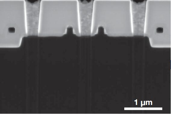
Before ion milling (FIB surface processing)
SE image
SEM: SU8200series
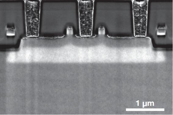
FIB Processing&Ion Grinding
SE image
SEM: SU8200series
BSE observation and EBSD grain orientation analysis of the sample.
Sample: Iron meteorite (section grinding)
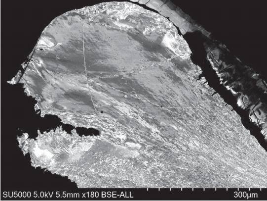
BSE image
SEM: SU5000
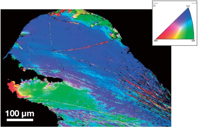
IPF*1 Map (Z)
*1 IPF: Inverse Pole Figure
The clarity of AFM magnetic domain images can be significantly improved by ion polishing the mechanically polished plane.
Sample: Neodymium magnet after heat treatment (flat grinding)
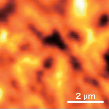
Before ion milling (mechanical polishing)
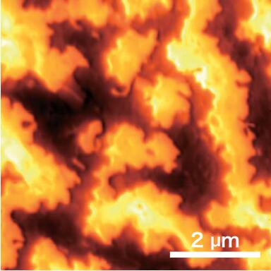
After ion milling
Sample provided by Daido Steel Co., Ltd
MFM * 2 Image SPM: AFM5300E
* 2: MFM (magnetic force microscope)
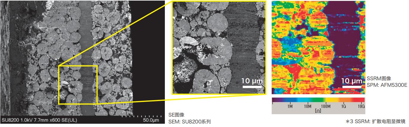
The abnormal contrast area in the SEM image was observed as a low impedance region through the SSRM * 3 image of SPM.
Sample: Lithium battery negative electrode (cross-section grinding)
| Project | IM4000 | IM4000PLUS | IM4000 | IM4000PLUS |
| Section grinding | Flat grinding | |||
| Use gas | Argon | |||
| Accelerating voltage | 0 to 6 kV | |||
| Maximum processing speed (material: Si) | ≧ 300 μm/hr*4 | ≧ 500 μm/hr*4 | - | |
| Maximum sample size | 20(W)× 12(D)× 7(H)mm | Φ50 × 25 (H) mm | ||
| Sample movement range | X±7 mm, Y 0 to +3 mm | X 0 to +5 mm | ||
| Intermittent processing | Standard configuration | |||
| Rotation speed | - | 1 r/m, 25 r/m | ||
| Swing angle | ±15°, ±30°, ±40° *5 | ±60°, ±90° | ||
| Tilt | - | 0 to 90° | ||
| Flow control method for argon gas (Ar) | Quality flow control | |||
| Vacuum system | Turbomolecular pump (33 L/S)+mechanical pump (135 L/min @ 50 Hz, 162 L/min @ 60 Hz) | |||
| Device dimensions | 616(W)× 705(D)× 312(H)mm | |||
| Weigth | Host 48 kg+mechanical pump 28 kg | |||
| IM4000/IM4000PLUS cooling temperature control unit | ||||
| Cooling temperature control function | Indirectly cooled by liquid nitrogen, temperature range: 0 to -100 ℃ | |||
| Optional | ||||
| Vacuum transfer box | Section grinding is available | − | ||
| Sectional Grinding Sample Stand (FP) | 100 μ m/circle * 6 | − | ||
| Processing real-time observation microscope | Dual eye type, triple eye type (with CCD) | |||
*4 The edge of the Si sheet protruding mask is 100 μm
*5 Swing angles during cooling are ± 15 ° and ± 30 °
*6 The movement accuracy of Mask has been improved, and its movement step size has become 1/5 of the current one
| Project | Content |
| Room temperature | 15 to 30 ℃ |
| Humidity | 45 to 85 % no condensation |
| Power supply * 7 | AC100 V(±10%)、50/60 Hz,、1.25 kVA |
| Ground wire | Less than 100 Ω |
| Project | Content |
| Argon | Purity 99.99% |
| Introduction of argon gas | 0.03 to 0.05 MPa |
| Argon inlet pipe*8 | 1/8 foot SUS piping (1/8 socket joint Swagelok), pressure reducing valve |
| Oxygen concentration meter*9 | It can be confirmed that the oxygen concentration is above 19% |
| Recommended placement table | 1000 (W) × 800 (D) × 700 (H) mm or more, with a load-bearing capacity of 70 kg or more (with only the lower limit of IM4000 placed) |
*7 The IM4000 and IM4000PLUS are equipped with a triangular plug power cord or M6 terminal block
*8 A pipeline connecting the argon gas source (argon cylinder) is required. Please prepare a pressure reducing valve that matches the gas supply equipment (argon cylinder)
*9 Ventilation and air quality measurement devices need to be prepared


 【 WeChat 】
Address:No. 501, Building 01, Northwest District, Suzhou Nano City,
No. 99, Jinjihu Avenue, Suzhou Industrial Park
Hotline:86-0512-62749825
Phone:86-18912625555 Mr Chen
Email:alan.chen@winwintek.com/ wuj@winwintek.com
Copyright © 2026 Win-Win Electronic Technology International Limited Su ICP NO.2025215884-1 Support:HuiCheng