

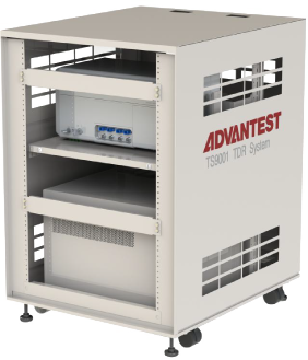
This system uses terahertz technology to accurately analyze the wiring quality of various cutting-edge semiconductor packages, such as flip chip BGA, wafer level packaging, and 2.5D/3D IC packaging. It is a TDR analysis system with world-class signal quality.
● High speed&high-resolution measurement
● Temperature regulation function
● Automatic TDR measurement
● Multiple analysis software can be provided
By achieving high resolution, world-class signal quality, non-destructive and high-precision analysis of wiring faults in advanced semiconductor packaging (failure analysis)
Due to the miniaturization of electronic devices and the development of high-density integrated structure technology, there is an increasing demand for systems that correspond to various analysis conditions and optimize analysis environments in semiconductor packaging fault analysis.
The TS9001TDR system utilizes our company's independently developed short pulse signal processing technology for high-resolution TDR measurement (time-domain reflection measurement), high-speed and high-precision non-destructive analysis, to detect and locate wiring faults within advanced semiconductor packages.
In addition, our TS9001 system can be connected to high-frequency probe systems owned/selected by customers, providing flexible solutions for testing body shapes (wafers, ICs) and fault analysis environments.
High speed&high-resolution measurement
● Can perform failure analysis for advanced packaging such as BGA, wafer level, 2.5D/3.5D, etc. with corresponding area array packaging
● The resolution of fault location can reach below 5 μ m
● The measurement takes 30 seconds (an average of 1024 times, which is 1/10 faster than our existing products)
Temperature regulation function
By connecting with a high-frequency probe system with heating system function, the sample can be subjected to fault analysis (failure analysis) evaluation under low/high temperature conditions
Multiple analysis software can be provided
Provide CAD Data Link (fault location indication software), which can display the fault area on CAD data. (optional)
Apply signals to the tested object and measure the time response waveform of the reflected signal from the input terminal to analyze the positions of open and short circuits.
Compare the waveforms of good and defective products, and use the peak positions and measurement points that only appear in defective products to determine the location of the faulty area.

Case study on TDR measurement analysis of transmission lines (length 4/6/20mm) that have already formed OPEN/SHORT structure
● In fault mode, a positive reflected pulse wave can be observed when OPEN, and a negative reflected pulse wave can be observed when SHORT
● The probe signal used in this system is related to Impulse, making it easy to determine the location of the fault point based on the peak position of the pulse

The TS9001TDR system serves as the standard equipment for the TDR Analyzer. In addition to displaying the waveforms of Reference and Sample with differences, it is also possible to detect changes in the waveform and estimate the distance from the pad to the fault point
When inferring the fault area, the CAD Data Link (optional software) can be used to map and display on the CAD wiring data as an auxiliary function for specific fault points

| Project | Content | |
System Composition | Measurement unit/Analysis unit/Terahertz signal transceiver/System control unit (system control and data analysis)/System bracket | |
System Specifications | Fault area detection resolution | <5 μ m @ 0 to 800ps,<10 μ m @ 800 to 1500ps time range |
Pulse rise time (response time) | <12ps | |
Maximum measurement distance | 100mm @ relative dielectric constant=5 | |
Measure time | 30sec@1 Measurement points (excluding automatic needle insertion Touch Down, average of 1024 measurements) | |
Needle insertion method | When selecting External Probe Control, it is automatic | |
Software specifications | TDR Analyzer | Standard combination |
CAD Data Link | Optional | |
External Prober Control | Optional | |
System Control | Standard Configuration | |
Product standard parameters | Product performance guarantee scope | Room temperature range: 23 ℃± 5 ℃ Relative humidity: 80% or below (no condensation) |
Working environment | Temperature range:+10 ℃ to+30 ℃ Relative humidity: 80% or below (no condensation) | |
Product storage environment | Temperature range: -10 ℃ to+50 ℃ Relative humidity: 80% or below (no condensation) | |
Power supply | Analysis Unit: AC100 V (100-120)/200V (220-240) ± 10%, 50/60 Hz, 250 VA System control unit: AC100 V (100-120)/200V (220-240) ± 10%, 50/60 Hz | |
External dimensions/weight | • Measurement unit: 430 (W) × 240 (D) × 220 (H) mm, 14kg or less • Analysis unit: 430 (W) × 540 (D) × 330 (H) mm, 30kg or less • Terahertz transceiver unit: 100 (W) × 340 (D) × 80 (H) mm, 1.5kg or less • System bracket: 860 (W) × 600 (D) × 700 (H) mm, 60kg or less • System control unit (host): 177 (W) × 519 (D) × 418 (H) mm, 16kg or less • System control unit (display): 520 (W) × 166 (D) × 351 (H) mm, 4.8kg or less • The size and weight of the system control unit may vary depending on the time of product launch | |

●Without prior notice, our company may make modifications to the product specifications and appearance mentioned in the product introduction. Please understand.

 【 WeChat 】
Address:No. 501, Building 01, Northwest District, Suzhou Nano City,
No. 99, Jinjihu Avenue, Suzhou Industrial Park
Hotline:86-0512-62749825
Phone:86-18912625555 Mr Chen
Email:alan.chen@winwintek.com/ wuj@winwintek.com
Copyright © 2026 Win-Win Electronic Technology International Limited Su ICP NO.2025215884-1 Support:HuiCheng